
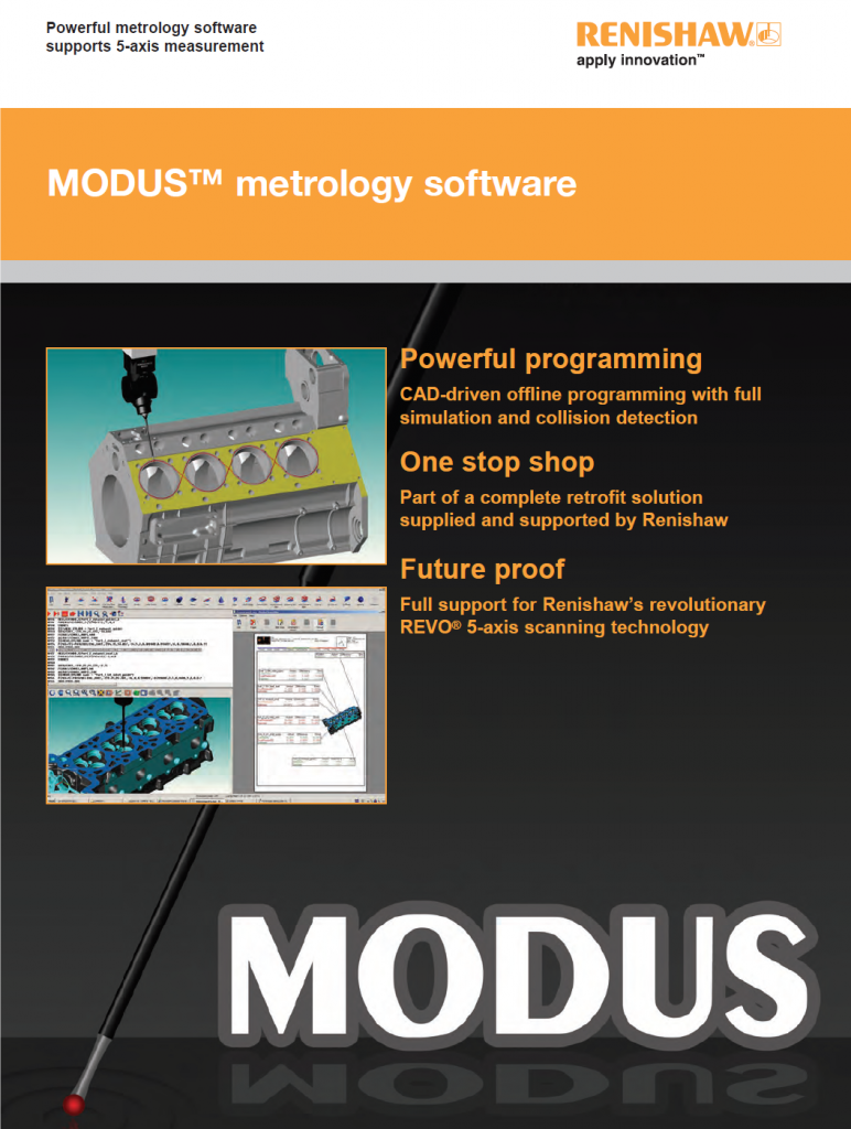
MODUS™ metrology software allows a part program to be created by having the computer write the program as to inspect your part. No Programmer Required!
Enhance your part program with simple one click editing, i.e. Change 4 point circles to 20 point circles on all you parts’ diameters with one click.
Is it really that easy to use?
Most CMM measuring software requires you to fly to a training center for 3 to 5 days of training. MODUS™ requires only two days of training, in your plant, on your CMM, inspecting your parts.
Simpler, faster, more accurate
- Graphical interface provides ease of use, one click probe selection for motorized heads and probe racks.
- Random part placement allows multiple parts of the same type to be inspected without expensive fixtures.
- Increase accuracy with the MODUS™ volumetric 3D error compensation.
Simplifying and enhancing the measuring process is what the “No Programmer Required” MODUS™ is all about. Its unparalleled, easy to use functions reduce the learning curve. Watch precision, productivity, and ultimately your bottom line… soar!
Measure Magic®
Probe any 2D or 3D feature and the MODUS™ knows, automatically, what type of feature you are measuring. Datum magic, an extension of our patented Measure Magic technology enable automatic part alignment to be performed by probing a sequence of datum features. Now you can inspect features as fast as you can think of them—and push the work, not the buttons. With our auto-repeat mode and a remote finish key, the operator can inspect an entire part without ever looking at or touching the computer. This is ideal for large CMMs, where the inspector isn’t close to the computer… a real time saver, from the leader in innovative metrology solutions.
Sensible Construction
Do you want the line that intersects two planes? Or the circle that’s created from the intersection of a plane and a cone? A distance between a 3D point and the center of a sphere? MODUS’™ intuitive user interface allows you to choose the construction and then select the features for use in the construction directly from the graphical part view. There is no need for multiple pages of different construction icons.
Automatic Part Programming
Measure your first part and MODUS™ learns the datums, measuring sequence, tolerance, and reporting functions. The computer writes the program, you simply select the program form an icon on the toolbar.
On screen part programming editing with point and click simplicity. Want to edit probe speed or probe path? Simply point and click.
Easy Probe Selection
The user can select from a variety of qualified probes and install the ones used most frequently. Just point and click to select them. Graphical interface simplifies motorized probe head rotations and styli rack destinations, point and click.
Multiple Options Part Views
Multi-Plan Views: MODUS™ offers true graphical part representation. Its Graphical Interface provides all the information you need in an intuitive format with four independent views: 3D modeling, XY, YZ, or ZX plan view. The tolerancing or construction features may be selected from any of the views.
Understandable Graphics
MODUS™ incorporates four graphical representations of the part: 3D, XY, YZ, ZX. Each view integrates full zooming and rotational functions and all four can be used interactively to select features for constructions, reporting, tolerancing, and color coded pass/fail indicators make it easy to determine how much of your part is within specifications.
Random Multiple Part Placement
MODUS™ measuring software allows random placement of multiple parts of the same type. Take one point on each part and you have full automatic part-to-part inspection without expensive features.
Part View Controls
Zoom in, zoom out, zoom to fit, zoom in on a selected area, pan and rotate functions, make MODUS™ the most complete CMM software available.
Quick View
Toolbar buttons allow the operator to view the part from any of a number of preselected orientations and elevations.
3D Feature Stamp
MODUS™ not only reports a numerical indication of the shape of your feature, it will also graphically show you the location of the points used to construct the features and any other points.
Full Geometric Tolerancing
If a part or feature doesn’t measure properly, you’ll know immediately. Out-of-tolerance features are clearly displayed in red. Tolerancing options include:
Location
- Bidirectionality
- Concentricity
- True Position (RFS, MMC, LMC)
Form
- Straightness
- Roundness
- Flatness
- Cylindricity
Orientation
- Perpendicularity
- Parallelism
Runout
- Angle
- Radius/Diameter
- Height
- Length
- Width
MODUS™ The Genius Is In Its Simplicity
No other system can offer you cost effective, advanced performance to keep you in control, even on highly complex jobs, day after day. All these features are standard on MODUS™.
- Conditional/Variable Capabilities
- Automatic Part Programming
- Random Multiple Part Placement
- Point & Click Editing
- Interactive Graphical Part View
- Form Indication/Statistics
- Unlimited Feature Storage
- Polar/Cartesian Coordinate Systems
- CAD Interface (Export to /DXF)
- Data Export (DDE)
- Group Tolerancing
- Multiple Reference Frames
- 3D Measure Magic® (pat. pending)
- Inch/Metric Conversion
Computer Specifications
| CPU | 933MHz PIII |
| Connection for: | XYZ Inputs |
| Connection for: | Touch Probe Inputs |
| Connection for: | Remote Foot Switch |
| RAM: | 256MB* |
| Floppy Disk: | 3.5″ 1.44 MB* |
| Hard Drive: | 10 GB* |
| CD ROM Drive: | 48X IDE* |
| Monitor: | 17″ Multimedia Super VGA* |
| Mouse: | Mouse and Mouse Pad Included |
| Operating System: | Microsoft Windows NT |
* Computer and monitor specifications are subject to change, other computer peripheral options available, ask you salesperson for more information
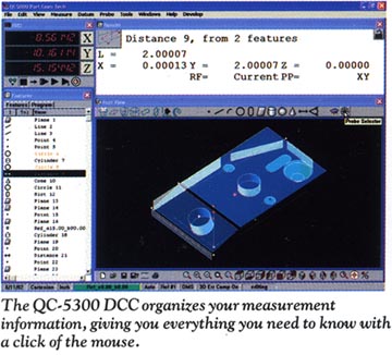
Point and Click Simplicity
MODUS™ utilizes the strength of the Windows 7™ operating system and allows you to make the most precise measurements using its interactive graphical user interface. Do you want the intersecting lines between two planes? Simply click on the “planes” in the Part View window and the line appears with all of its coefficients displayed in the easy to read Results window. Add the “point and click” ease of Windows™ and our unique Measure Magic® functionality and you can probe all the part characteristics without even touching the computer.