
At last, an easy to use, CMM retrofit software package all inspectors can operate. Metronics’® Quadra-Chek 5000 CMM software was voted #1 for “ease of use” by our twelve Field Service Engineers. Our Service Engineers are familiar with all the CMM software and they all agree: “The QC-5000 is by far the easiest to use CMM software.”
Is it really that easy to use?
Most CMM measuring software requires you to fly to a training center for 3 to 5 days of training. The QC-5000 requires only one day of training, in your plant, on your CMM, inspecting your parts.
Simpler, faster, more accurate
Pull-down menus, user definable window positions and tool settings combine with 3D geometries, constructions and intersections to make measuring simpler, faster and more accurate than you ever imagined.
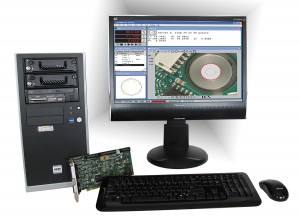
MOST CMMS MANUFACTURED IN THE 1980S AND 1990S ARE WELL MADE, STURDY MACHINES WITH GOOD MOTOR DRIVE SYSTEMS. WE RETROFIT YOUR CMM WITH QC-5300 DCC SOFTWARE AND REPLACE THE CONTROLLER, AMPLIFIERS, JOYSTICK BOX AND COMPUTER. THIS RESTORES YOUR CMM TO STATE-OF-THE-ART EQUIPMENT. IT WILL INCREASE PRODUCTIVITY, EXTEND THE LIFE OF THE CMM AND INCREASE THE CMM’S ACCURACY WITH VOLUMETRIC ERROR COMPENSATION.
Simplifying and enhancing the measuring process is what the QC-5000 is all about. Its’ unparalleled, easy to use function reduce the learning curve. Watch precision productivity, and ultimately your bottom line… soar!
Measure Magic®
Probe any 2D or 3D feature and the QC-5000 knows, automatically, what type of feature you are measuring. Datum magic, en extension of our patented Measure Magic technology enable automatic part alignment to be performed by probing a sequence of datum features. Now you can inspect features as fast as you can think of them—and push the work, not the buttons. With our auto-repeat mode and a remote finish key, the operator can inspect an entire part without ever looking at or touching the computer. This is ideal for large CMMs, where the inspector isn’t close to the computer… a real time saver, from the leader in innovative metrology solutions.
Sensible Construction
Do you want the line that intersects two planes? Or the circle that’s created from the intersection of a plane and a cone? A distance between a 3D point and the center of a sphere? The QC-5000’s intuitive user interface allows you to choose the construction and then select the features for use in the construction directly from the graphical part view. There is no need for multiple pages of different construction icons.
Self-Programming
Measure your first part and the QC-5000 learns the datums, measuring sequence, tolerances, and reporting functions and then visually leads you through subsequent part inspections by following the flashing cursor. You simply select the program from an icon on the toolbar.
Easy Probe Selection
The user can select from a library of qualified probes and install the ones used most frequently in the toolbar. Just click the mouse to select them. The user can select probe tips from a start probe by moving the probe in the direction of the tip to be activated… the operator doesn’t have to touch… or look at… the computer!
Multiple Options Part Views
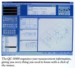
MULTI-PLAN VIEWS: The QC-5000 offers true graphical part representation. Its Graphical Interface provide all the information you need in an intuitive format with four independent views: 3D modeling, XY, YZ or ZX plan view. Tolerancing or construction features may be selected from any of the views.
Part View Controls:
Zoom in, zoom out, zoom to fit, zoom in on a selected area, and rotate functions, make the QC-5000 the most complete CMM software available.
Quick View:
Toolbar buttons allow the operator to view the part from any of a number of preselected orientations and elevations.
Layer Control:
Inspectors can view the entire part at once, or organize features into “layers” making the graphical interface easier to use and understand. Ideal for complex parts with multiple geometries, layer control gives the user control over which features are visible and which are hidden for use later in the measuring routine.
Full Geometric Tolerancing
If a part or feature doesn’t measure properly, you’ll know immediately. Out-of-tolerance features are clearly marked in red. Tolerancing options include:
Location:
- Bidirectional
- Concentricity
- True Position (RFS, MMC, LMC)
Form
- Straightness
- Roundness
- FLatness
- Cylindricity
Orientation
- Perpendicularity
- Parallelism
Runout
- Circular
Size
- Angle
- Radius/Diameter
- Height Length
- Width
Understandable Graphics
The QC-5000 incorporate four graphical representations of the part: 3D, XY, YZ, ZX. Each view integrates full zooming and rotational functions and all three can be used interactively to select features for constructions, reporting, tolerancing, and color coded pass/fail indicators make it easy to determine how much of your part is within specifications.
3D Feature Stamp
The QC-5000 not only reports a numerical indication of the shape of your feature, it will also graphically show you the locations of the points used to construct the features and any outlier points.
DDE and CAD Interface
The Windows® operating environment allows you to interface the QC-5000 to other WIndows programs such as Microsoft® Excel or with Windows based SPC packages. The QC-5000 can also download to a CAD system throgh IGS or DXF file formats.
Automatic & Magnetic Planes
The QC-5000 automatically recognizes and reports n which plane you have probed (XY, YZ, ZX). Using our unique Magnetic Planes function, and features that are probed above or below primary planes can be automartically “snapped” to the nearest primary plane making measurements more axccurate and the grapics more understandable.